
Steve has been around the calibration industry his whole life. His father, Mark Toll, founded Fox Valley Metrology in 1996, when Steve was only 6 years old. Steven went on to graduate from Milwaukee School of Engineering, one of the most challenging and accolated technical universities in the country. This lifelong immersion in the industry has led him to become the Vice President of Sales for Fox Valley Metrology since 2014.
Thread Inspection 101 Part II - Thread Form

This is Part II of our Thread Inspection 101 series.
In Part I, we discussed the basics of thread measurement and dove into what thread gages are.
Before we continue any further into our deep dive on thread gaging, it is imperative that we first gain a solid understanding of exactly what we are measuring. As discussed early in Part I of this series, thread measurements may be the most complex of all dimensional measurements. There are numerous different measurements that must be made in order to verify that a part is within spec. Today, we will get into those attributes.
Thread Form Basics
To understand any type of threading, the following basic terms are critical to understand. Nearly all threads (at least the common ones) will have these critical components of form. Consider this the building blocks of your complete knowledge of thread measurement.
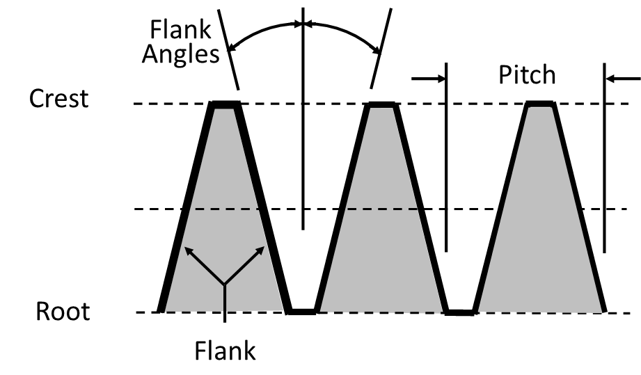


- Crest - The height at which an external thread is raised, or the depth at which an internal thread is indented.
- Root - The deepest part of the thread groove.
- Flank - The sides of the thread form, connecting the crest and the root.
- Flank Angles - The angle between the flank and a line perpendicular to the axis of the thread.
- Pitch - The distance between corresponding points on adjacent threads.
All of these attributes are great, but rarely are these the measurements that actually get called out in a specification. As you can imagine, calling out each of the above for one simple thread would be a daunting task. As such, the standardized method relies on a few unique measurements.
While these measurements are the same for each thread type, it does get a little confusing when discussing internal threads vs. external threads. Because of this, it is worth diving into each on their own.
External Thread Basics
To understand these additional critical dimensions, let's first dive into external threads, as they are a bit more easy to understand and visualize.
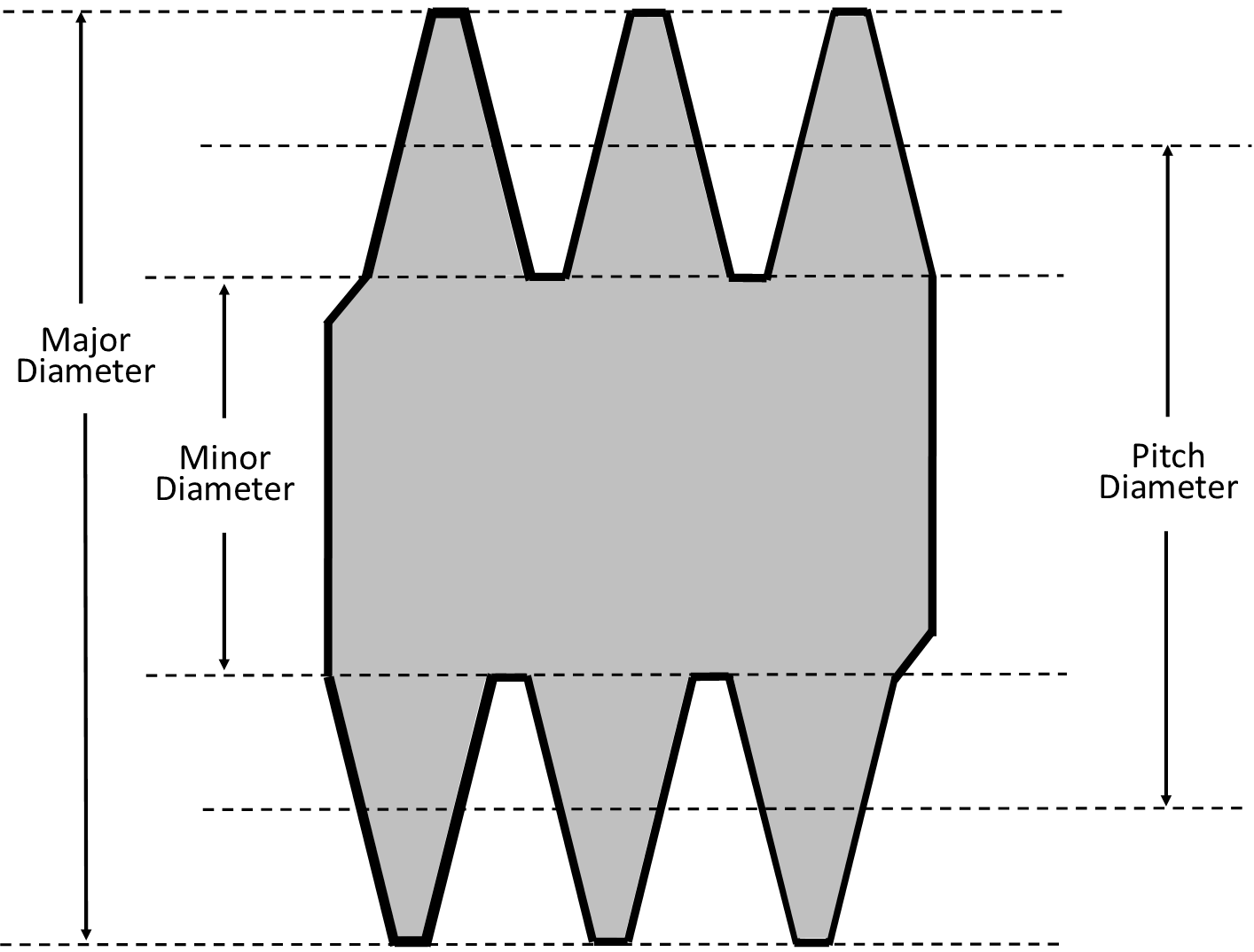

- Major Diameter - The distance between a line that touches the crests on either side of the thread form. This is the largest diameter of the thread. The major diameter dictates all other dimensions, internal and external, of a thread design.
- Minor Diameter - The distance between a line that touches the roots on either side of the thread form. This is the smallest diameter of the thread. The minor diameter of an external thread must clear the mating component's internal thread minor diameter.
- Pitch Diameter - The distance between a line that splits the crest and root on either side of the thread form. The pitch diameter controls the tightness of fit on the mating component.
Internal Thread Basics
The basics of an internal thread are essentially the same as those of an external thread.
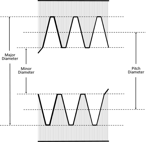
- Major Diameter - The distance between a line that touches the roots on either side of the thread form. This is the largest diameter of the thread. The major diameter must clear the major diameter of the mating component's external thread.
- Minor Diameter - The distance between a line that touches the crests on either side of the thread form. This is the smallest diameter of the thread. The minor diameter controls the strength or shear of the thread design.
- Pitch Diameter - The distance between a line that splits the crest and root on either side of the thread form. The pitch diameter controls the tightness of fit on the mating component.
These three dimensions are absolutely critical to understand in the sizing and design of a thread system. Thus, it is absolutely critical you understand those dimensions when it comes time to measure and inspect threaded components.
Quantity of Threads
However, there is one major specification of a thread design yet to be discussed. That specification deals with exactly how many threads there are in a given thread design. This concept is vitally important to ensure that the coupled components are going to mate together properly. If the threading of an external and internally thread component are different they will either seize or strip the threading resulting in an unusable connection.
In specifying this criteria, there are two main approaches:
- Threads Per Inch (TPI)
- Pitch
As you will see, the two are inverse of each other.
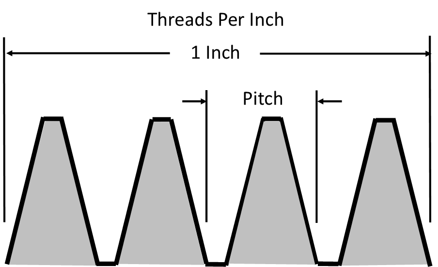
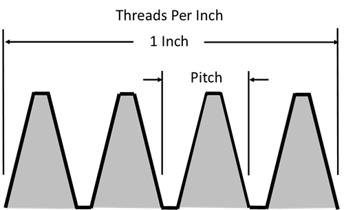
Threads Per Inch (TPI)
Threads per inch is exactly that: the number of threads within one inch, along the length of the thread. This designation is only used with American fasteners, due to the use of the inch within the specification. It is commonly abbreviated to TPI.
Pitch
As described earlier, pitch is the distance between corresponding points on adjacent threads. This can be measured from any point within the thread, such as the crest or the root as well. This designation is used to specify metric threads.
With this understanding of the basics of thread form, you now have a very solid foundation on thread measurement that we will build off of to discuss common nomenclature systems in Part III of our Thread Inspection 101 series.
Interested in having your thread gages calibrated? Check out our Thread Ring Calibration Services or our Thread Plug Calibration Services today!
Interested in purchasing a thread gage? Please submit a request today.
comments powered by Disqus