
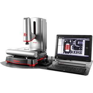
Starrett AVR200 FOV CNC Field of View Vision System
Price by Request
Savings: N/A
The AVR200 CNC field of view “FOV” vision system offers 8″ x 4″ x 8″ travel, optional Z-axis measuring, a powerful MetLogix software control system, interchangeable telecentric or zoom optics and LED illumination. These systems are rapid video-based FOV CNC measurement systems, which reduce measurement time and are ideal for quality assurance, inspection labs, manufacturing, assembly and research facilities. A precision mechanical bearing X-Y-Z stage and column along with interchangeable telecentric lenses gathers data accurately and repeatably for the MetLogix software. This compact bench top FOV system is simple, quick and powerful!
Starrett AVR200 FOV CNC Field of View Vision System Features
Features
- System Type: Bench Top
- Part View Orientation: Vertical
- X-Y-Z Travel: 8″ x 4″ x 8″ (200mm x 100mm x 200mm)
- CNC: Standard
- X-Y Accuracy (µm): E2 = 1.9 µm + 5L/1000
- Z Accuracy (µm): E1 = 2.5 µm + 5L/1000
- Scale Resolution: 0.1 µm
- Multi-Sensor Compatible: No
- Base: Granite
- Control System / Software: MetLogix M3
- Display: 21″ Touchscreen PC
- Zoom Optics – Standard: 6.5:1
- Zoom Optics – Optional: 12.0:1
- Digital Video Camera: 1 MP Color
- Surface Ring Illumination: LED
- Transmitted Illumination: LED
Options
- Z Axis Measuring: Optional
- Zoom Optics – Optional: 12.0:1
- Telecentric Lenses (Required on FOV & HDV): .3X, .5X, .8X, 1.0X, 2.0X, 4.0X
- Workstation Base, Extension and Swing Arm: Optional
- Part Fixturing: Optional
- Video Pixel Calibration Standard: Optional
- Calibration Standards: Optional
Software
The AVR Series is built around a 24″ touch screen and PC which runs MetLogix™ M3 CNC software under Windows® 10 Professional. M3 software supports 3-axis measurements and 2D geometrical constructs (points, lines, angles, rectangles). The screen displays a live video image of the part plus geometry tools and digital readings. The part image can be resized using pan and zoom, and measurements can be taken by simply tapping a feature on the screen. With the M3 DXF/FOV option CAD files can be imported over a network and be automatically compared to the actual part.
Features:
- 24″ (60cm) color graphic touch-screen monitor and PC
- M3 controller housed in Z column
- Full CNC control of X-Y-Z position and optical zoom
- Manual X-Y-Z position control via joystick and trackball
- Windows® 10 Professional operating system
- Wi-Fi network connectivity
- Video edge detection
- X-Y-Z measurements
- 2D geometric constructs plus height
- FOV measurements integrated with X-Y stage motion
- CAD file import and export
- Automatic comparison of measurements to CAD files
Optics
The MVR Series is available with dedicated 6.5:1 zoom optics or with a quick-change bayonet lens mount which accepts 6.5:1 zoom optics and a choice of 6 telecentric lenses for accurate field-of-view measurements. The 6.5:1 zoom lens is available with coaxial surface illumination and with auxiliary lenses to multiply magnification by 0.5X, 1.5X or 2.0X.
| Optical Parameter | Telecentric Optics (FOV Models) | 6.5:1 Zoom Optics | 12:1 Zoom Optics | |||||
|---|---|---|---|---|---|---|---|---|
| Optical Magnification on CCD | 0.30X | 0.50X | 0.80X | 1.0X | 2.0X | 4.0X | 0.47X to 3.0X | 0.47X to 3.0X |
| Total Magnification on Monitor | 13X | 22X | 36X | 45X | 89X | 178X | 31X to 198X | 26X to 310X |
| Field of View Width, mm | 24 | 14 | 9 | 7 | 3.5 | 1.8 | 10 to 1.6 | 12 to 1 |
| Working Distance, mm | 110 | 110 | 110 | 110 | 110 | 110 | 88 | 88 |
| Camera CCD | 1/1.8″ | 1/1.8″ | 1/1.8″ | 1/1.8″ | 1/1.8″ | 1/1.8″ | 1/3″ CCD Array | 1/3″ CCD Array |