Steve has been around the calibration industry his whole life. His father, Mark Toll, founded Fox Valley Metrology in 1996, when Steve was only 6 years old. Steven went on to graduate from Milwaukee School of Engineering, one of the most challenging and accolated technical universities in the country. This lifelong immersion in the industry has led him to become the Vice President of Sales for Fox Valley Metrology since 2014.
Thread Inspection 101 Part III - Thread Designations (Imperial)

This is Part II of our Thread Inspection 101 Series.
In Part I, we discussed the basics of thread measurement and dove into what thread gages are. In Part II, we discussed the basics of thread form.
If you have been following along in our Thread Inspection 101 Series, you should now have a very solid foundation in the different attributes of a standard thread form. As you have seen, there are many different aspects that go into a quality machined thread.
As you can imagine, because of all these different aspects, an easy to use designation nomenclature system was needed to be developed. Of course, things can be as simple as having one system that covers the entire world, so two systems were created, one for the Imperial system and one for the Metric system.
Today, we will dive into the Imperial thread designation system and will cover the Metric thread designation system in Part IV of the series.
Imperial Thread Designations
The thread designation system that we use here in the US is the Imperial thread system. Other common names for this are "Standard", "English" or most commonly just simply "Inch".
All Imperial thread designations were consolidated to the Unified Thread Standard (UTS)in 1949 to ensure greater consistency among different manufacturers. This standard is maintained by ANSI.
Below is a breakdown of this designation system and its components:
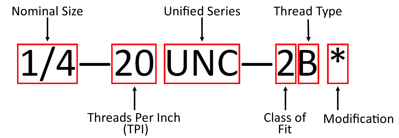
Nominal Diameter
The nominal diameter is the size used for easy identification of a thread. The number is the theoretical diameter from which the design size limits are derived by the application of tolerances and allowances. This number is essentially the nominal size of the major diameter of the thread.
Most often these sizes expressed in fractional values of an inch. However, some of the smaller size are designated by a one or two digit number. In all cases, the larger the number, the larger the size.
Threads Per Inch (TPI)
The next section describes the quantity of threads in an inch of the thread. This is discussed in length in Part II.
It bears noting that, in general, the smaller the nominal size, the higher the threads per inch count.
Thread Series
The next section describes the series of thread being described. There are numerous different series within the umbrella of the UTS, but all of those will start with "UN".
The last character (or characters) of this nomenclature describe the pitch of the thread, along with other uniquely identifying information. Some common series are:
- UN - Constant pitch series
- UNC - Coarse pitch series
- UNF - Fine pitch series
- UNEF - Extra fine pitch series
- UNJ - Constant pitch series, with rounded root on external threads & thread ring gage
- UNJC - Coarse pitch series, rounded root on external threads & thread ring gage
- UNS - Special diameter, pitch or length of engagement
- UNJF - Fine pitch series, rounded root on external threads & thread ring gage
- UNJEF - Extra fine pitch series, rounded root on external threads & thread ring gage
Class of Fit
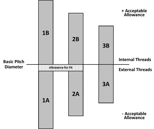
This is the term used to designate the "tightness" of two mating components. This results from a combination of tolerances and allowances applied to the basic size of each component.
It is very important that these classes are specified to allow for interchangeability.
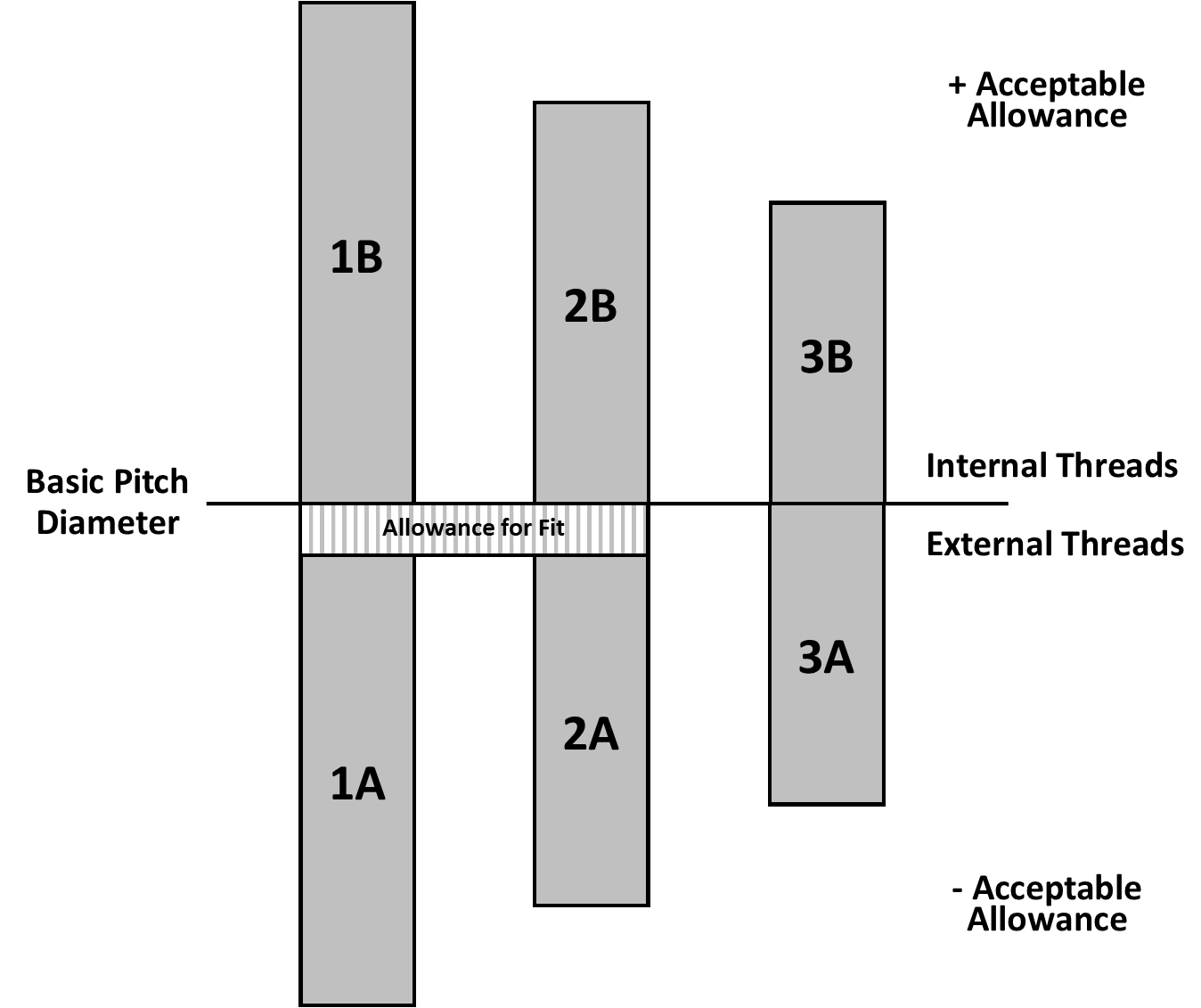
The three common classes of fit are a simple system of 1, 2 or 3. These classes of fit vary from loose (1) to tight (3). More specifically:
- 1 - Use for applications where a liberal tolerance is required to permit easy assembly, even with slightly marred threads. An additional allowance for fit is added to the external thread component.
- 2 - Most commonly used class for general applications. An additional allowance for fit is added to the external thread component. This is commonly referred to as the "nuts and bolts" fit because of the guaranteed gap between the mating components, where tightness is accomplished by contact against a face.
- 3 -For Applications where accuracy of thread elements are highly important. This is commonly referred to as the "machine fit".
A visual representation of this concept is shown here:
Thread Type
The thread type designation is a very simple one and has two options:
- A = External threads
- B = Internal threads
As we will find out in a subsequent post, type A threads also clearly denote that the thread gage is either a ring gage or a set plug gage. Type B threads also clearly denote a working plug gage.
Modification
This last section for designation is rarely used, but still important. This is where any modification to the standard designation would be called out. For example, "LH" would denote a left-handed thread (no more righty-tighty, lefty-loosie!).
In Part IV of our Thread Inspection 101 series, we will explore the metric thread designation system and its intricacies.
Interested in having your thread gages calibrated? Check out our Thread Ring Calibration Services or our Thread Plug Calibration Services today!
Interested in purchasing a thread gage? Please submit a request today.
