Skip to the content

Menu

Thread Inspection 101 Part VI - Thread Plugs

Thread Inspection 101 Part VI - Thread Plugs

This is Part VI of our Thread Inspection 101 Series. 

In Part I, we discussed the basics of thread measurement and dove into what thread gages are. In Part II, we discussed the basics of thread form. In Part III, we discussed the intricacies of the Imperial thread designation system, while in Part IV, we discussed the intricacies of the Metric thread designation system. In Part V, we dove into the complicated world that is the theory behind thread inspection.


Now that we have fully dove into the weeds on the theory behind thread inspection, it is time to pull this series back out into the world of the practical.

As discussed in Part V, the complex geometry of thread inspection is prohibitive for most inspections needed on the shop floor. It is just not practical to complete a full dimensional inspection of every threaded component that leaves your facility.

Luckily, we have thread gages available as a very quick check for all threaded components. There are two main thread gages:  the thread ring for inspecting external threads and the thread plug for inspecting internal threads. This gaging system allows us to shorten inspection times down to a matter of seconds for each component. As a result of this tremendous efficiency, thread gages have become ubiquitous in machining centers around the world and are now one of the most common gages in existence.

We will begin our deep dive into thread gages with a much closer look at thread plugs and their usage.

Thread Plug Design

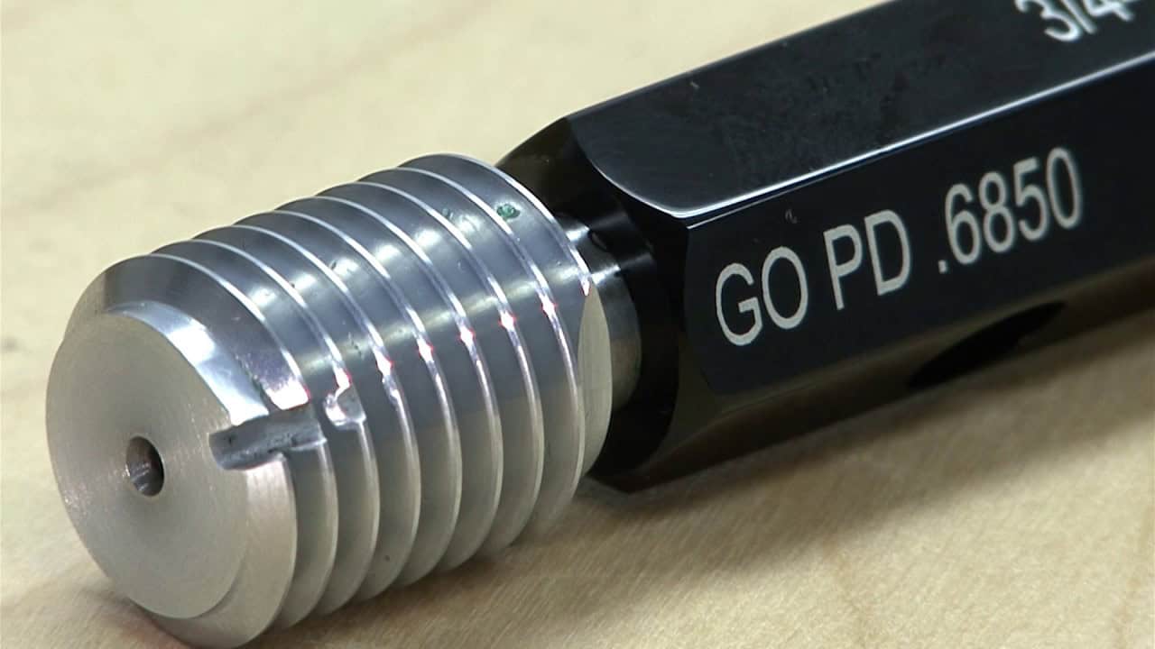
Thread plugs are machined Go/No-Go gages that contain external threading machined to a very specific thread size. They are used for checking internally threaded components (i.e. nuts).

Thread Plug

All thread plugs are classified as an attribute gage, meaning they do not provide feedback on what the exact size of the dimension is. They are performing a functional inspection to verify that the internal threads being inspected are within the accepted tolerance.

Commonly, thread plugs come in what is known as an assembly, containing a Go plug, a No-Go plug and a handle that hold the two together. This is very convenient, because, as we will cover soon, an inspection requires both ends to be used.  As is seen in the above picture, many times the appropriate ends are marked accordingly on the handle (in this case with green for Go and red for No-Go). Oftentimes, the handle will be marked with the nominal size of the gage as well as the Go and No-Go pitch diameters.

As for the plug members themselves, there are three main configurations:  taperlock, reversible and trilock.

Taperlock Thread Plug Members

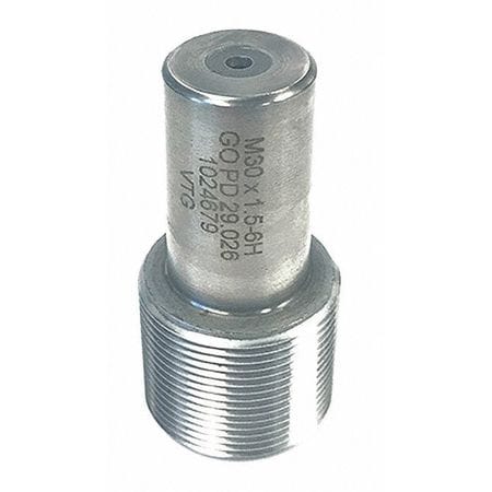
This is the most common style of working thread plug members. This style allows for a quick, easy replacement of a worn member in an existing handle. When a member is beyond its usable life, it can be easily removed and a new replacement inserted in its place.

Taperlock Thread Member

Reversible Thread Plug Members

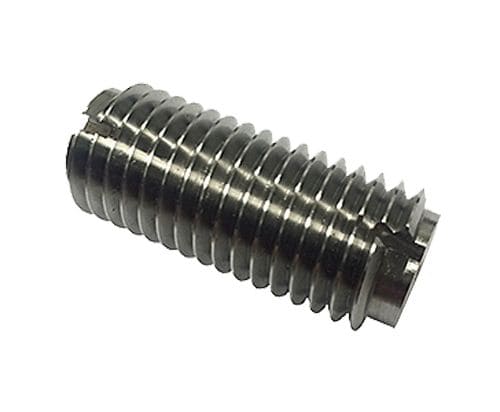
These members contain threading over the whole length of the member. The unique design allows for the member to be reversed within the handle once it reaches the end of its usable life. When doing so, the worn portion is turned inside the handle and the unused portion becomes the working portion of the plug. Essentially, this act doubles the life of the member, making it ideal for high volume applications.

Reversible Thread Plug Member

Trilock Thread Plug Members

The trilock system contains a bolt that threads in along the axis of the member and locks it to the handle. This system is best suited for large thread plugs (typically over 1.5 inches). Due to the size of these thread plugs, it is not uncommon to see them as individual plugs, rather than assemblies.

Go Thread Plug Members

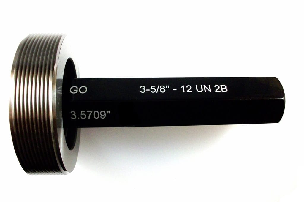
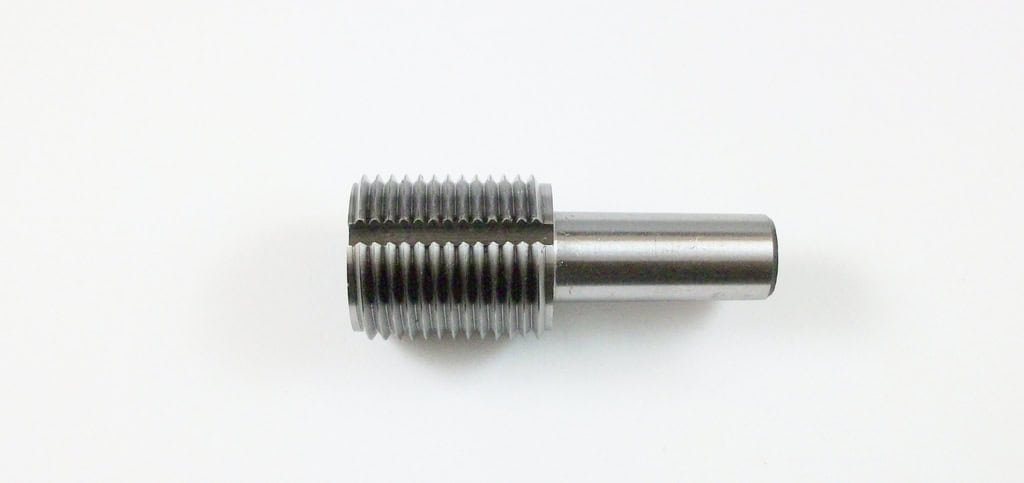
The Go thread plug is machined to a plus tolerance making it so the member is at the maximum material limit. It is commonly manufactured longer than the No-Go member, due to the fact that it should reach the full depth of a threaded component. Additionally, in larger sizes, the Go member is commonly machined with a groove in it. This groove is present to allow for the easy clearing of any debris inside the threaded component to prevent any unnecessary wear of the gage.

Go Thread Plug MemberGo Thread Plug Member

Usage

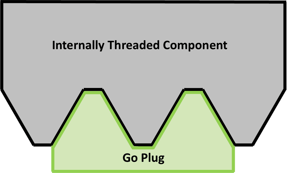
The Go member is used for verification of an internally threaded component. 

Plug Gage Contact (Go)Plug Gage Contact (Go)

It inspects the following:

  • Minimum allowable major diameter
  • Minimum allowable pitch diameter
  • Flanks
  • Lead

In use, the operator is to thread the Go member into the internally threaded component. The member should pass freely and easily through the whole length of the component. If it makes it all the way through the thread, the part passes. If it gets stuck or requires any use of force to make the member thread, the product is smaller than the minimum allowable size and should be failed.

Understanding this is very important. Sometimes, you can force the gage through the product. However, doing so is not doing anyone any favors. Forcing the Go member through the component can actually "grind" down the product making it seem like it is acceptable. This act will compromise the integrity of it. Additionally, it will slowly but surely wear out the plug member as well.


No-Go Thread Plug Members

The No-Go thread plug is machined to a minus tolerance making it so the member is at the minimum material limit. As mentioned above, the No-Go member is commonly manufactured shorter than the Go member. This is because, as you will see, the No-Go member is not intended to travel the whole depth of the threaded component. Shorter equals cheaper. Additionally, the No-Go member commonly is machined with a ground down crest, as this portion of the plug is not used needed.

Usage

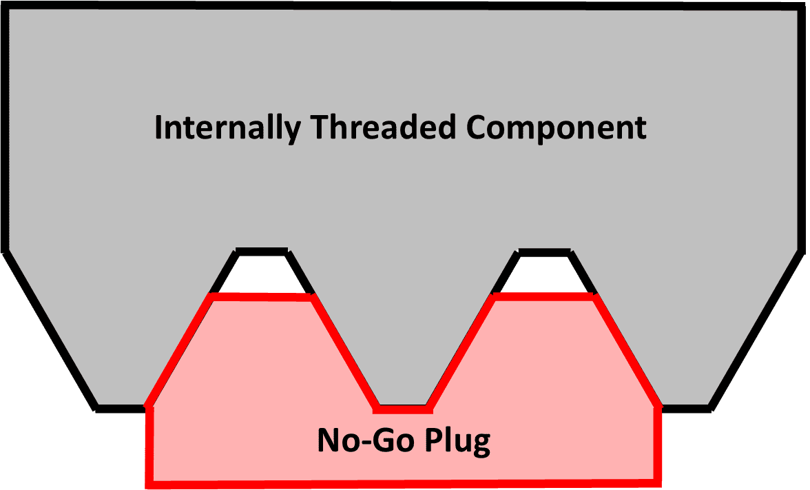
Obviously, like the Go plug member, No-Go thread plug member is used used for verification of an internally threaded component. 

Plug Gage Contact (No-Go)

However, it is only used to inspect the maximum allowable pitch diameter. (Side note:  you may have noticed that neither Go nor No-Go members address the minor diameter of a component. If required, this check must be performed by other means, such as a bore gage).

In use, the operator is to thread the No-Go member into the internally threaded component.

Unfortunately, there is a difference in the criteria on when to pass a product between the inch and metric system. For the inch (Imperial) system, the No-Go member should not pass more than three complete turns into the product. If, of course, the product is thin and has less threads than that, modification of this rule would be required. For the metric system, the criteria is that the plug should have a definite drag before the second turn.

If the No-Go member engages with the product more than the allotted amounts for either system, the product being inspected is larger than the maximum allowable size and should be failed. 

Inspection Nuances

As discussed above, the inspection process is pretty simple and easy to understand. However, the inspection process is open to some ambiguity. After all, what is a "definite" drag? Also, how can you know that a machinist is not forcefully pushing Go members through product?

Additionally, there is a somewhat common and very confusing inspection problem that arises when tools and taps are worn or chipped. In this instance a hole will accept the No-Go member, but not the Go member. How is this possible? If you recall, the No-Go member only checks the pitch diameter of the product. As such, it is not inspecting the deepest points (major diameter) of the thread. Without knowing what is occuring, the machinist may adjust to cut the thread larger on the next piece. This would be a mistake, as it is actually lead to overcutting the thread pitch diameter. Confusing, isn't it?

It is because of this ambiguity and complexity that consistent and ongoing training should be provided to all users of thread plugs within your company. This is your best shot at guaranteeing consistency across all users.

Setting Plugs

Up until this point, our entire conversation has focused on working plugs - i.e. the plugs you would use to inspect a product. However, there is another type of plug, the setting plug, which is used in conjunction with a thread ring to help "set" the ring gage to the correct size. As such, we discuss the setting plug in detail alongside the thread ring in subsequent posts of this series.


In Part VII of our Thread Inspection 101 series, we will explore the ins and outs of thread rings and their usage.

Interested in having your thread gages calibrated? Check out our Thread Ring Calibration Services or our Thread Plug Calibration Services today!

Interested in purchasing a thread gage? Please submit a request today.

About the author

Steve Toll

Steve has been around the calibration industry his whole life. His father, Mark Toll, founded Fox Valley Metrology in 1996, when Steve was only 6 years old. Steven went on to graduate from Milwaukee School of Engineering, one of the most challenging and accolated technical universities in the country. This lifelong immersion in the industry has led him to become the Vice President of Sales for Fox Valley Metrology since 2014.

comments powered by Disqus

Precision Matters

Give your precision measuring equipment the care it deserves today.